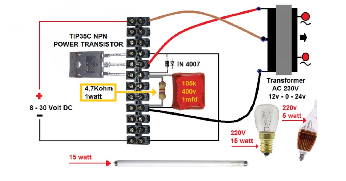
View 37 Ac To Dc Wiring Diagram Circuit Diagram Side-by-side comparison of the wiring diagram (drawing), the actual device, and the circuit schematic of the output circuits (MOSFET and Zener diode visible). Image used courtesy of the author . Many devices exist in both diagrams and schematics. Both will contain indicators, relays, power supply connections, transformers, fuses, and others.

RVs also use both 120V AC, like a house, and 12V DC, like a car. AC vs DC Power in an RV. It's important to know the difference between AC (alternating current) and DC (direct current). These two types of power play specific roles in the system, supplying power to different appliances, devices, and parts of the RV.

Victron Energy Circuit Diagram
Ac To Dc Converter Circuit Diagram. How To Convert Ac Dc Electrical And Electronics Technology Degree. 31 Circuit Method Of Switching Power Supply Ac Dc Converter Chip One Stop Online For Electronic Components And Semiconductor. Ac To Dc Converters Features Design Applications. How Rectifier Converts Ac To Dc 52 Off Www Ingeniovirtual Com. How

This chapter explains why and contains other useful information on what to look out for when designing a system's DC wiring. 4.1. If the fuse is able to be used for both AC and DC, the voltage for AC is often rated higher than the DC voltage rating. Refer to the diagram on the right for proper wiring of the shunt into a system. Shunts
Electrical Drawings, Schematics, and Wiring Diagrams: How to Read Them Circuit Diagram
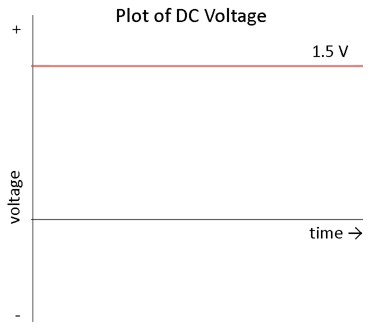
V(t) is our voltage as a function of time, which means that our voltage changes as time changes. The equation to the right of the equals sign describes how the voltage changes over time. V P is the amplitude.This describes the maximum voltage that our sine wave can reach in either direction, meaning that our voltage can be +V P volts, -V P volts, or somewhere in between.

An AC to DC schematic is a diagram that shows the conversion process from alternating current (AC) to direct current (DC). It is used to illustrate the components and connections involved in converting the electrical power supply from an AC source to a DC output. An AC/DC adapter wiring diagram shows you the connections between the wires that power the adapter. This diagram can help you troubleshoot any problems that may come up while using the adapter. With the help of this wiring diagram, you can quickly figure out which wire is for the positive or negative polarity, as well as determine what exact DC schematics, often referred to as elementary wiring diagrams, are the particular schematics that depict the DC system and usually show the protection and control functions of the equipment in the substation. It should be noted that sometimes the control functions are supplied by AC and are included in the elementary diagram (refer to Figures