
RFid Based Attendance Management System Circuit Diagram GRANT ALL PRIVILEGES ON attendance_system.* TO 'attendance_admin'@'localhost'; Before we create our tables, we need to utilize the "use" command so that we are directly interacting with the "attendance_system" database. Begin interacting with the database by running the following command. use attendance_system;

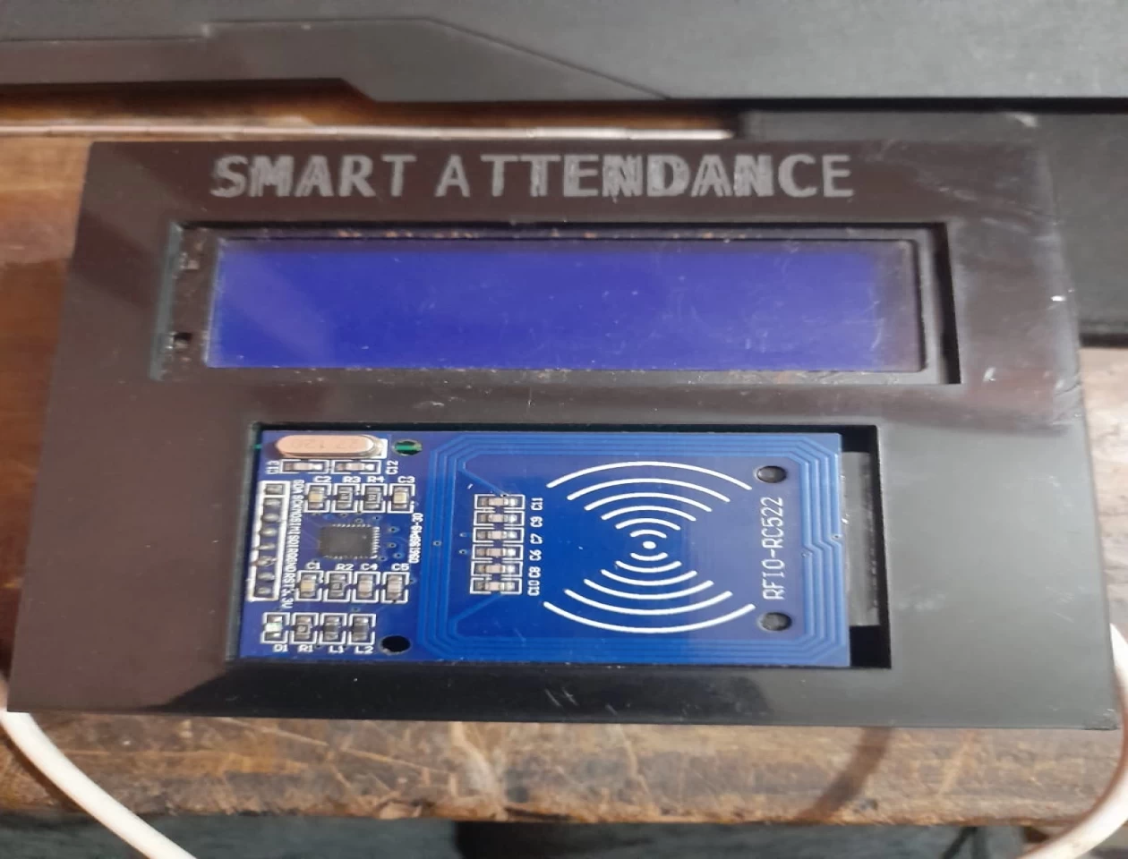
In this project we have designed RFID Based Attendance System using Arduino UNO and RFID MFRC522 Module. Arduino Firebase Project Description: Arduino Firebase, Students Attendance system using RFID and GSM- In this tutorial, you will learn how to make an advanced level student attendance system using Google Firebase Database, Arduino, GSM Sim900A Module, MFRC522 RFID Receiver Module, RFID Tags, and a 16×2 LCD.This is an IoT based project and used for monitoring the students' attendance from This is where an RFID-based attendance system comes into play. By leveraging the power of RFID technology and Arduino, we can create a system that is both reliable and easy to use. This blog post will guide you through the process of building your own RFID-based attendance system, complete with detailed explanations and full Arduino code.
Arduino Firebase Database, Students Attendance system using RFID GSM Circuit Diagram
We don't need any introduction regarding the RFID based attendance system, it is being used in colleges, office, libraries to know how many times a person or how many number of people has come in and out at what time. In this project we will be constructing a simplest RFID based attendance system which does not overcomplicate the project. First, we'll set up the RFID component based on the system described in the Viral Science Creativity tutorial: By following these steps, you may create a two-step attendance system that combines
*RFID SDA to arduino Digital pin D10. *RFID SCK to arduino Digital pin D13. *RFID MOSI to arduino Digital pin D11. *RFID MISO to arduino Digital pin D12. *RFID GND to arduino GND. *RFID RST to arduino Digital pin D9. *RFID 3.3V to arduino 3.3V. RTC module connections. *RTC module SCL to arduino A5. *RTC module SDA to arduino A4. Learn how to create your own RFID Attendance System using Arduino in this step-by-step tutorial. The system allows you to track and manage attendance effortl
