Embedded System Interfacing Circuit for Microcontroller Circuit Diagram microcontroller interfacing circuits revolution Revolution Education Ltd. Business Innovation Centre, Innova Park, Mollison Avenue, Enfield, Middlesex, EN3 7XU Tel: 020 8350 1315 Fax: 020 8350 1351 Email: info@rev-ed.co.uk Web: www.rev-ed.co.uk

The advantage here is that the optical switch can be used for input interfacing harmful voltage levels onto the input pins of microcontrollers, PICs and other such digital circuits or for detecting objects using light as the two components are electrically separate but optically coupled providing a high degree of isolation (typically 2-5kV). Micro-controller is a small Computer on a single Integrated Circuit. It is compact brain which drives most of today's automation systems. This tutorial section is for students and hobbyist who are interested in learning basics of Micro controllers, its interfacing circuits & various communication protocols used for interfacing IC's to microcontrollers.

Microcontroller Interfacing with Different Elements Circuit Diagram
GENERAL INTERFACING • Various logic families (5V, 3.3V, 2.5V, 1.8V, etc.) • Often necessary to convert from one voltage domain to another (e.g. a 3.3V microcontroller communicating with a 5V sensor) • Different level translation techniques available depending on: •Duplex (one-way communication or bidirectional?) •Number of lines (1 line?
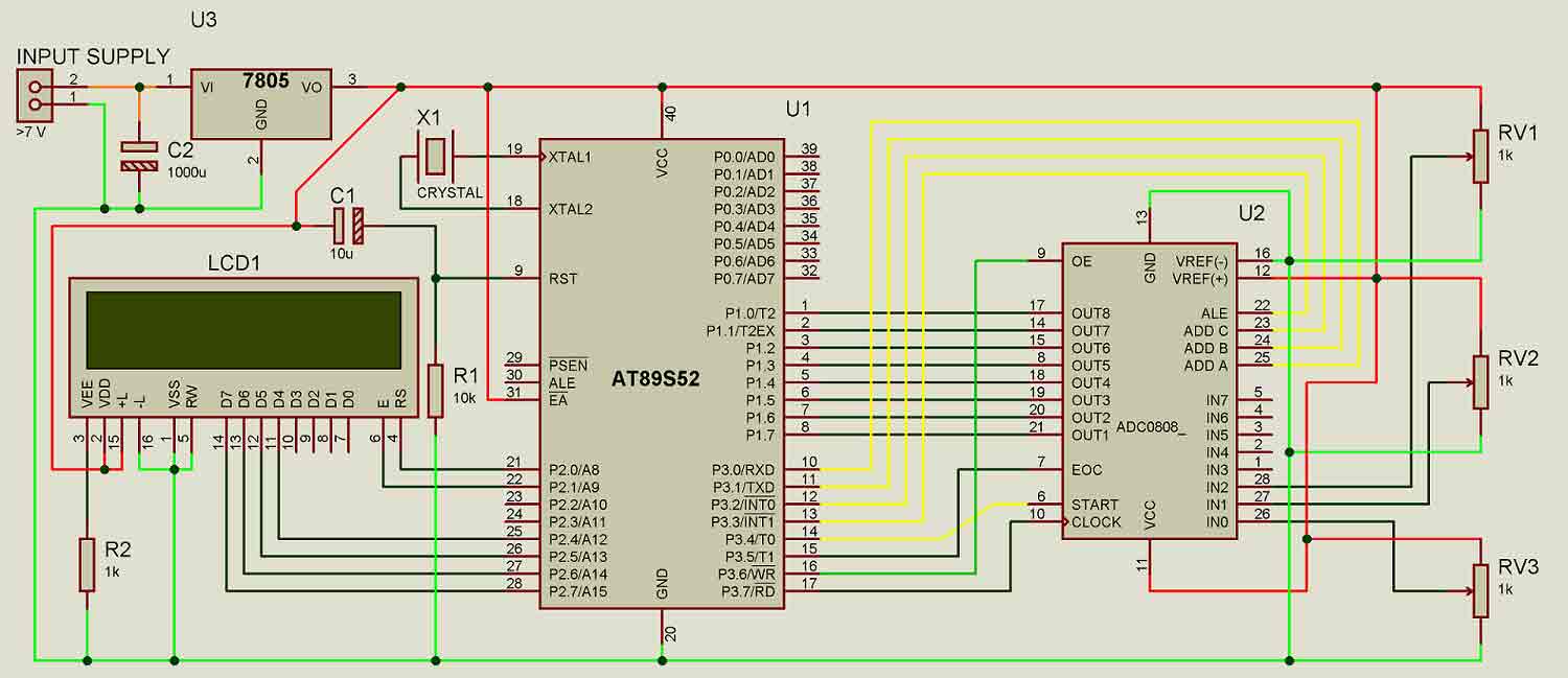
Circuit Diagram and Explanation. Circuit diagram for LCD interfacing with 8051 microcontroller is shown in the above figure. If you have basic understanding of 8051 then you must know about EA(PIN 31), XTAL1 & XTAL2, RST pin(PIN 9), Vcc and Ground Pin of 8051 microcontroller.
PDF Microcontroller Interfacing Techniques Circuit Diagram
Microcontroller Interfacing with Different Elements. This is a Step By Step Guide to Interfacing Different electronic Elements with Microcontrollers. Rating: 4.3 out of 5 4.3 (42 ratings) Circuit Design, Simulation, and PCB Fabrication. Arduino, PIC Microcontroller, and Raspberry Pi.

DC motor driver interfacing; H-bridge circuit and it's working. L293D for DC Motor Interfacing with 8051 Microcontroller; Circuit Components and Proteus Schematic; 8051 Code and its Explanation; Related Articles. In case you liked this article and looking for more similar content, check out these links below: Many interface methods have been developed over the years to solve the complex problem of balancing circuit design criteria such as features, cost, size, weight, power consumption, reliability, availability, manufacturability. Many microcontroller designs typically mix multiple interfacing methods. In a very simplistic form,

LCD Interfacing with 8051 Microcontroller Circuit Diagram
Interfacing is a crucial aspect of microcontroller applications. It is the process that allows a microcontroller to connect and communicate with external devices such as sensors, actuators, memory devices, and other microcontrollers. This article provides an overview of the basics of interfacing techniques with microcontrollers.