Digital Circuit Diagram In a digital voltmeter, the analog voltage is converted into a digital value and displayed on a digital screen, making it easier to read and interpret. To start building your digital voltmeter circuit, you will need a few basic components, including an analog-to-digital converter (ADC), a microcontroller, a voltage reference, and a display. But to measure greater levels of voltage, something more is needed. To get an effective voltmeter meter range in excess of 1/2 volt, we'll need to design a circuit allowing only a precise proportion of measured voltage to drop across the meter movement. This will extend the meter movement's range to higher voltages.
The transistors are BC640, however you may try other transistors like 8550 or 187 etc. The proposed digital voltmeter, ammeter circuit module can be effectively used with a power supply for indicating the voltage and current consumption by the connected load through the attached modules. Referring to the circuit diagram below, the 3 digit digital display module is build through the ICs CA 3162 Step 3: After determining the full-scale current rating of your meter movement, you must accurately measure its internal resistance. To do this, disconnect all components from the previous testing circuit and connect your digital ohmmeter across the meter movement terminals. Record this resistance figure and the full-scale current figure Mr Swagatam hi; when I test the circuit with 3 single display s assigned for measuring the 0-99 volt, I can see the value 00.0 and the decimal display fluctuates between 1 and 2 (100-200 mV). however there is no any voltage value if other 12 volt voltage source is added to the circuit as their grounds are common. Another point is that there is no display of the numbers but except dot if the

25V Digital Voltmeter using AVR Microcontroller Circuit Diagram
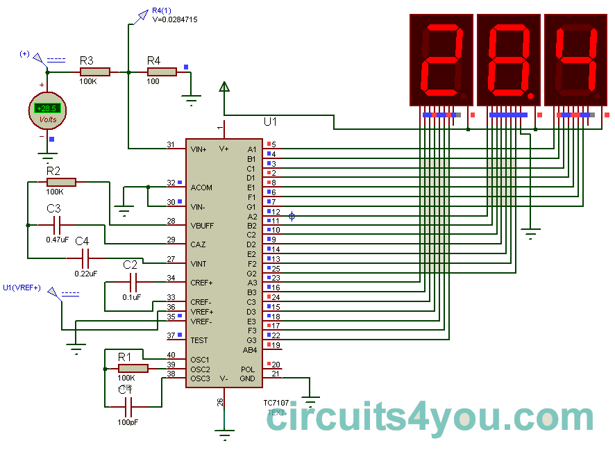
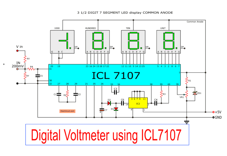
In this project we have a tendency to design a circuit to build an electronic voltmeter while not making use of any microcontroller. Here we have a tendency to employing a very moderate IC for voltage activity particularly ICL7107/CS7107. Making use of ICL7107, we are able to build correct and really low price digital voltage measurement meter. Function 3: AC voltage measurement. We can design the AC voltage measurement circuit. By adding the AC to DC converter circuit. They have a relationship together. As shown in Figure 3. Figure 3: Digital AC voltmeter circuit without transformer. The AC voltage is measured to reduce voltage same the DC voltmeter circuit.
Working of this Digital Voltmeter Circuit is very simple. ADC inside the IC is integrating converter or Dual type Analog to digital converter. I have same design ckt of volt meter but the problem be is when I calibrate 5v =12.00 v the the meter reading will changes 0.10 v & it will slowly decresing reading , it's take 2 to 3 min for showing